FR-4, Tg, Thickness and Copper Weight: The Four Numbers on Every PCB Order
Material, Tg, thickness and copper weight decide how your board handles heat, current and connectors. Here is what each number means and when to move away from the defaults.
Microplacer team · 15 November 2026 · 5 min read
 PCB Manufacturing
Open any PCB order form and four fields are waiting for you before you even think about colours or finishes: base material, Tg, board thickness and copper weight. They look technical, and many first-time buyers simply leave them alone. Good news — the defaults are sensible. Better news — once you know what each number means, you will also know the few moments when changing it is worth it.
Why the defaults suit most hobby and prototype boards
The usual starting point is FR-4, Tg135, 1.6 mm thick, with 1 oz copper — the board most connectors, enclosures and assembly lines expect. A microcontroller board, sensor breakout or student project rarely needs anything else.
Staying on the defaults also keeps ordering simple. FR-4 boards up to 16 layers get an instant online price, with GST and shipping included and a free 100% flying-probe electrical test on every board. The rule of thumb is easy: change a field only when your design gives you a clear reason.
FR-4 and what Tg really means for reflow and heat
Think of FR-4 as fibreglass cloth soaked in epoxy, cured into a rigid sheet and clad with copper foil. Flame-retardant additives give it the "FR" in its name. It is cheap, predictable and inside nearly every gadget you own.
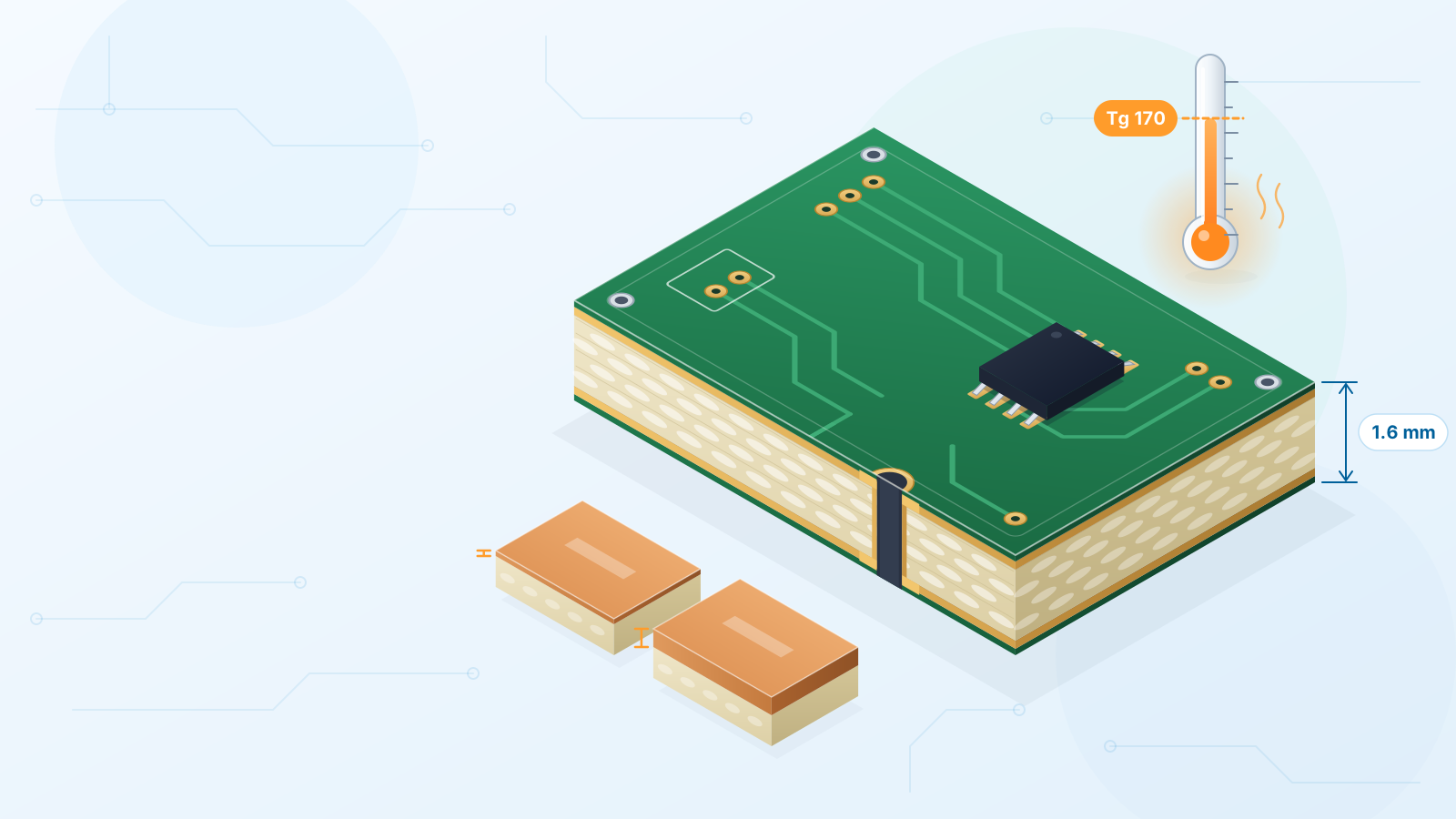
Tg stands for glass-transition temperature: the temperature at which the cured epoxy changes from glassy and rigid to rubbery. Under Tg, heating makes the board grow only slightly. Past it, the growth rate jumps — and because the glass cloth holds the board in its plane, most of that extra growth goes into the Z-axis. Every plated hole is a copper tube running through that thickness, so it gets stretched. Enough hot cycles and the barrel or its joint to the pad can crack.
Every board passes Tg briefly during soldering, so the real question is margin: a higher Tg means less time in the fast-expanding zone. In practice:
- Around 130–140: plenty for a simple board that sees one or two ordinary soldering passes.
- Around 150–155: worth it when both sides are reflowed, there will be rework, or the product runs warm.
- 170 and above: the safer pick for thick, high-layer-count boards, hot lead-free profiles and harsh, hot environments.
Lead-free alloys melt hotter than tin-lead, and a thick stack needs longer in the oven to heat through, which is why high-layer-count boards are normally built on higher-Tg laminate. The calculator shows which Tg options go with your layer count.
Choosing board thickness: connectors, rigidity and edge fingers
The thickness you order is the finished figure — laminate plus copper plus mask — and 1.6 mm is the value the rest of the hardware world assumes. Before picking anything else, check three things:
- 1Connectors and hardware. Through-hole connectors, board-to-board headers and some press-fit or snap-in parts specify a board thickness range. Go outside it and pins may not seat or solder properly.
- 2Rigidity. Thin boards (0.4–1.0 mm) suit wearables and small modules, but large thin boards bend and can warp in reflow. Thick boards (2.0 mm and above) stay flat under heavy parts or repeated plugging.
- 3Edge fingers. A board that plugs into a card-edge socket must match the socket — usually 1.6 mm. Too thin and contact is weak; too thick and it will not go in.
Copper weight: current, heat and fine-line trade-offs
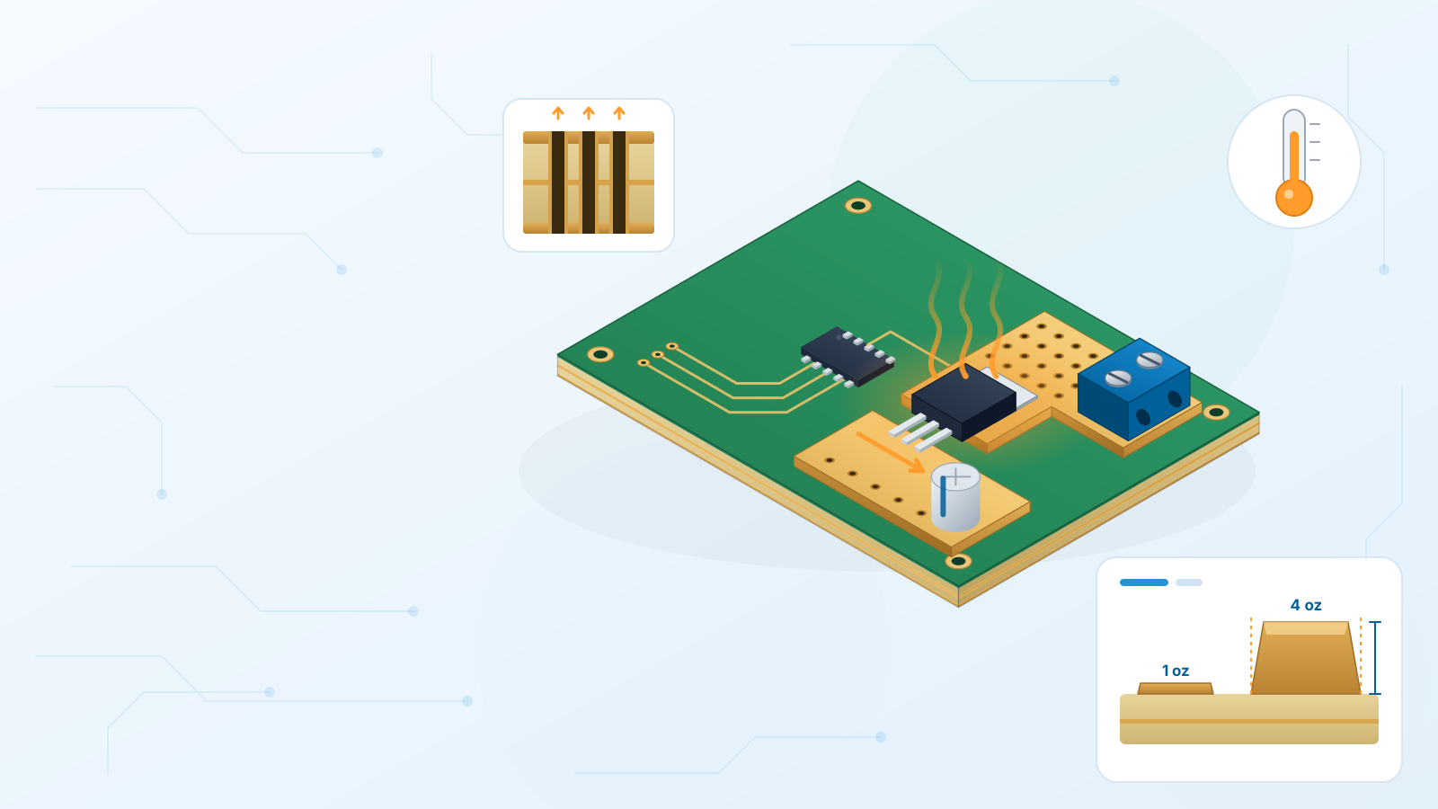
The "oz" figure is an old unit that stuck: it is how many ounces of copper would cover a square foot of board. In thickness terms 1 oz is close to 35 µm and 2 oz close to 70 µm. A thicker layer gives each trace more cross-section, so it carries more current for the same temperature rise and spreads heat further across the board.
The catch is etching: thick copper is harder to etch into narrow traces and small gaps, so heavier copper raises your minimum width and spacing. Dense digital boards usually stay on 1 oz; motor drivers or battery boards may want 2 oz or more.
A quick way to decide
- 1List your highest-current paths: power input, motor, LED or heater outputs.
- 2Run them through an IPC-2152 (or IPC-2221) trace-width calculator with the temperature rise you accept.
- 3If there is room to make the trace wider, do that and keep 1 oz — usually the cheaper fix.
- 4If there is no room to widen, move to 2 oz and update your design rules before routing.
When to consider flex or other materials
FR-4 struggles with two jobs: pulling heat out of hot parts, and keeping losses low at RF and microwave frequencies. If the board must bend, choose flex (polyimide), which is also priced instantly online. For heat, look at aluminium or copper core boards; for RF, at laminates such as PTFE. These special materials are quoted by our team.
When to move away from each default
| Field | Default | Change it when… | Change to |
|---|---|---|---|
| Material | FR-4 | The board must bend, shed a lot of heat or carry RF/microwave signals | Flex, metal core or an RF laminate |
| Tg | ~135 | Double-sided reflow, rework, high layer count or a hot operating environment | 150–155, or 170+ for thick multilayers |
| Thickness | 1.6 mm | A tight enclosure, a connector with a different range, or a large board that must stay flat | Thinner (0.6–1.0 mm) or thicker (2.0 mm+) |
| Copper | 1 oz | A power path cannot simply be made wider | 2 oz or heavier, with wider gaps |
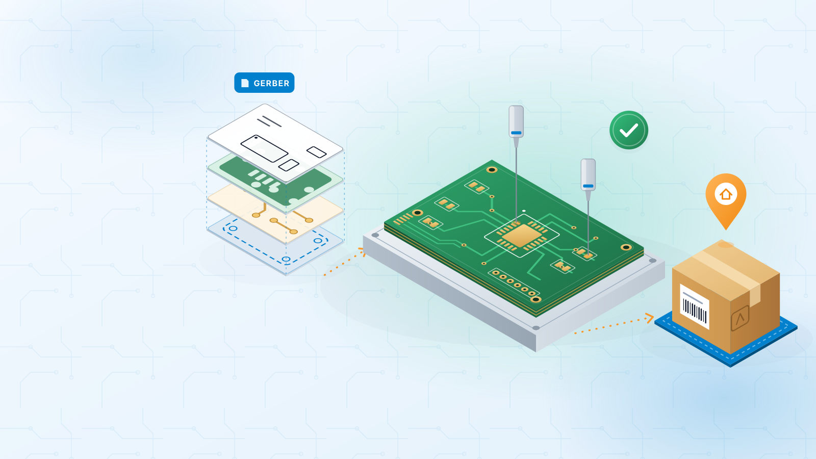
Treat this as a starting point — your connectors, enclosure and current needs have the final say, and our engineers check every file before production. The PCB materials and thickness guide lists every option by layer count, and our PCB capabilities page has the full manufacturing limits. When your fields are set, upload your Gerber and get an instant price.
#fr4#tg#board-thickness#copper-weight#pcb-materials
Get an instant PCB quote